Industrial Wastewater Treatment in Kuwait
Dr. Nayef Al-Mutairi
Arabian Gulf is a semi-enclosed sea located in the Middle East and is connected to oceans through the narrow 55-km Strait of Hormuz.
The reuse of wastewater is now regulated by several sets of standards: including one governing the discharge of toxic materials to sewers and others that established standards for reuse of wastewater and the processing and use of sludge.
Progress in wastewater reuse in Kuwait has been significant.
Industrial Pollution
•Solids.
•BOD/COD (biological oxygen demand/chemical oxygen demand).
•Acidity/alkalinity (pH).
•Toxic Organics.
•Gases produced in the collection system under anaerobic conditions.
•Gases introduced through direct discharge, leaks, or released in an acidic environment.
•Fats/Oils/Grease.
•Heavy Metals.
•Nutrients.
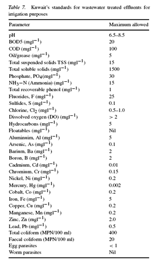
Maximum limit for pollutants of industrial Dischrage water to be dischraged in the Kuwait Sea

Case 1
Slaughterhouse Wastewater Treatment
•Five major slaughterhouses in Kuwait processing approximately 2.0 million animals in the year of 2001.
•Producing waste effluents in very high quantities and concentration of organic matter which creates an economical and ecological burden to the plants responsible for their treatment.
•Typically, slaughterhouse effluents are much more concentrated than domestic wastewater.
•Main contributors of organic load to these effluents are fat and lard, undigested food, blood, suspended material, urine, loose meat, soluble proteins, excrement, and inorganic particles.
•One of the major problems of slaughterhouse wastewater treatment is that very large reactors are often needed to provide sufficient capacity.
Contact stabilization (CSB) 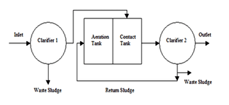
•CSB process presents an elegant solution for the treatment of high strength wastewater.
•Rapid uptake of colloidal substrate onto the microbial biomass by physical absorption, followed by enzymatic breakdown and use of the resulting soluble material.
•Reduced tankage requirements and resistance to shock loadings.
•CSB process also control filamentous bulking in activated sludge systems.
Coagulation/Flocculation
•Aluminum salts and polymer compounds.
•The removal of COD, SS and turbidity from slaughterhouse wastewater ranged from 3% to 20%, 98% to 99%, and 76% to 93%, respectively, when alum was used in the range of 100–1000mg/L, with pH in the range of 4–9.
•When polymer was used instead, the COD and SS removals ranged between 9% and 43% and between 95% and 96%, respectively.
•Effluent discharge standards with regard to COD and SS removals could be safely obtained at 2–4mg/L concentrations of polymer or the use of 300–600mg/L alum with pH in the range of 4–9.
Influence of alum and polymer dosage on water quality parameters of coagulated, settled mixed liquor

Effluent acute toxicity scales of Microtox based on 5- and 15-min EC50 values


•Alum at low concentration was less toxic, showing an EC50 between 25% and 70%.
•When alum concentration varied between 500 and 1000 mg/L ,the toxicity was significant (EC50=3–20%).
•Coagulants can adversely affect the characteristics of sewage sludge, which could affect the sludge disposal method.
•Coagulants increased the toxicity of the sludge as a result of the removal of toxic wastewater constituents or as a result of the toxicity of the coagulant itself.
PLANT DESCRIPTION
•An advanced wastewater treatment plant (WWTP) in Hawalli, Kuwait, that was originally designed in the mid 1990s to accommodate wastewater from the slaughterhouse.
•The WWTPs original design average capacity is:


Contact Stabilization Plant Operational Range

Operating matrix for the contact and aeration process
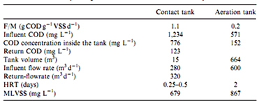
kinetics Data

* Increased floc loading in the contact tank beyond an optimum value would result in a lower substrate removal efficiency and a lower floc uptake during the high kill season.

* Whereas, the aeration tank demonstrated excellent removals of COD (22% in the case of the contact tank and 78% in the case of the aeration basin).

COD concentrations throughout the contact stabilization process

Data published in the literature on the performance activated sludge system

Solids inventory of the contact stabilization process

Sludge volume index (SVI) in the contact tank during high kill and low kill season


•High soluble COD and BOD5 removal efficiencies were consistently achieved throughout the study despite dramatic changes in influent wastewater composition throughout each processing day.
•CSB was effective in maintaining a good mixed liquor SVI and in controlling filamentous organisms.
•Controlling internal recirculation to maintain a contact loading up to 150mg COD g-1 VSS in the contact tank, generally resulted in good settleability as measured by sludge volume index (SVI) values, which were consistently below 150mL g-1 MLSS.
•Higher contact loadings of about 300 mg COD g-1 VSS , resulted in a significant deterioration in SVIs, FU, and SER.
Case 2
Al-Rawabi Dairy Wastewater and Solid Treatment
Several major factors were identified from the data obtained from the old dairy wastewater treatment plant.
- Plant suffer low F/M ratios during off-days, leading to sludge bulking and unstable and poor efficiency.
- The old plant do have an equalization tank. The size was inadequate to alleviate the fluctuation in flow and organic loading.
- The wastewater were nutrient deficient. –Seasonal temperature variations are also found to have a significant effect on the microbial population, leading to the decrease in plant efficiency.
- The fluctuation in flow, organic loading, and pH magnified the impact on the conventional continuously-stirred tanks.
Quantity
•More than 190 gal/d/cow (flushing manure and milk parlor ).
•Parlor (cleanup and sanitation) 10%.
•Cow washing 40%.
•Manure flushing 40%.
•Miscellaneous 10%.
Exiting Problems
•Odor generation.
•Ground water contamination.
•Surface water pollution.
•Land Wastage.
•No treated wastewater for flushing water reuse.
•Labor intensive.
BOD & Chloride
•The average BOD value is considerably higher than domestic wastewater.
•The high level of chloride and phosphorus are more unique to the dairy industry.
•Chloride is present in milk at a concentration of approximately 1000 mg/L. Since it is a conservative parameter, chloride is not removed in a conventional biological wastewater treatment plant.
•Performed chloride minimization efforts have been able to reduce chloride levels from above 1000 mg/L down to the 200 to 400 mg/L range.
•It is, therefore, believed that through best management practices within the production plant dairies will ultimately achieve water quality based chloride limits.
Phosphorus
•Milk has a phosphorus content of 930 mg/L.
•Al-Rawabi dairy facilities have used phosphoric acid for scale removal.
•40-50 % of the phosphorus discharged to the wastewater treatment plant was contributed by the phosphoric acid.
•Perform a phosphorus minimization evaluation within the processing plant. Substituted nitric acid or a phosphoric/nitric blend for straight phosphoric acid.
Evaluation of Existing Technology Alternatives

Liquid stream treatment

SBR Cycle

SBR Unique Characteristics
•Simple installation.
•Less equipments/space requirement.
•Long SRT (solid retention time).
•Low cost.
•Meeting flexible reuse purpose.
•Easy operation and maintenance.
•High removal efficiency for TCOD.
•Short time period for starting up.
•Odor elimination.
•Reuse of treated wastewater.
Purification of Dairy effluent

SOLIDS STABILIZATION AND TREATMENT
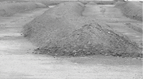
•Composting is the natural decomposition of organic materials by microorganisms that require oxygen (aerobic).
•Several factors that affect the success of the composting process: vcarbon and nitrogen ratios (C:N ratio) vmoisture content vparticle size voxygen concentrations vTemperature.
•The proper mix of composting materials requires both carbon and nitrogen at a 25:1 to 30:1 ratio and to keep odor at minimum, and the environment will be conducive to the growth of microorganisms.
•Sawdust was added as a carbon source due to its highly absorbent characteristics.
•The compost mixture’s moisture content was controlled to 50 to 60 percent.
•Moisture concentrations of greater than 60 percent will generate odors and increase the chance of leachate (runoff) from the compost pile.
•Aeration by turning introduces air into the compost pile. Optimal composting temperatures range from 110 to 150°F.
•Compost piles need a layer of inactive material (approximately 1 foot thick) to insulate the pile and maintain high temperatures.
Conclusion
•The problems of odor, well water contamination, treated wastewater for reuse of floor flushing were eliminated.
•Co-existing of agricultural production system and protection of environmental quality was possible.
Case 3
Kuwait National Petroleum Company-Mina Al-Ahmadi Refinery
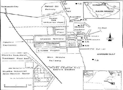
•Shuaiba Industrial Area in Kuwait is one of the largest industrial complexes in the Gulf region (23 million m2).
•There are eleven major industries, including:
- the petrochemical company.
- three refineries.
- two desalination power plants.
- a melamine company.
- an industrial gas corporation.
- a paper products company.
- two steam electricity generating stations.
- several other small scale industrial plants.
Characteristics of KNPC Industrial Wastewater (mg/l)
|
KNPC Sh. R |
KNPC MAB |
KNPC New Ref. |
KNPC Old Ref. |
LPG |
|
|
Load rate m3/d |
6500 | 7500 | 3000 | 1000 | 1300 |
|
BOD |
- | 147 | 50 | - | - |
|
COD |
300 | 320 | 119 | 400 | 320 |
|
TSS |
25 | 40 | 100 | 40 | 0 |
|
TKN |
50 | 40 | 25 | 20 | 0 |
|
NH3-N |
46 | 35 | 20 | 20 | 0 |
|
Oil |
17 | 27 | 10 | 28 | 4 |
|
H2S |
20 | 10 | 0.1 | 0 | 0 |
|
Cr |
- | - | 0.22 | - | 0 |
|
pH |
- | - | - | 8.2 | 7.5 |
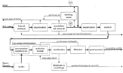
KNPC-MAA Refinery WWTP Block flow diagram

Effluent Water to Gulf
•Combination of treated effluent water and return sea cooling water.
•Combined effluent discharged to gulf meets Kuwait-EPA standards.
•In Refinery side treated effluent water will meet K-EPA standards (without mixing with seawater) POST REVAMP.
•In gas plant area treated effluent water meets K-EPA standards and hence not included in the REVAMP project.
Kuwait-EPA standards for Effluent Water
| Parametes |
EPA Limit (ppm) |
Treated water (ppm) | Final Effluent (ppm) |
| PH | 6-8 | 8 | 8.2 |
| BOD | 30 | 127 | 28 |
| COD | 200 | 372 | 115 |
| Oil and Grease | 10 | less than 4 | less than 4 |
| Tss | 10 | 15 | 8.5 |
| Ammonia | 3 | 57 | 1.8 |
| Sulfides | 0.5 | 0 | 0 |
Effluent Water to REVAMP Project

K-EPA Standards Vs MAA Gas Plant

Effluent Water
•REVAMP of wastewater treatment facilities.
•Treated effluent water will meet Kuwait-EPA standards without mixing with seawater.
Effluent Water Treatment Facilities
•SOUR water: SWT unit.
•Seawater effluent: Seawater Guard Basin.
•Semi oily water: Rainwater Guard Basin.
•Oily Water –Old Refinery: Dorr Oliver –RMP/FUP: CPI (Corrugated Plates Interceptor) /Aerated Lagoon –LPG Plant: CPI.
Reuse of Civil Equipment
•Separators
- Reuse as a clarifier
- Additional piping
- Increased overflow rate
- Not advised (too costly)
•Rain water guard basin (RWGB)
- Free oil removal
- New DAF feed pumps
•Aerated lagoon
- Holding tanks (not recommended; smells and cover is too costly)
- Pre-aeration
- SBR
Recovery/Reuse of treated effluent water
•Irrigation water.
•Fire water ponds (evaporation losses).
•Make-up evaporative cooling towers.
•Process (Utility) water: Removal of residual organics, Solids.
•Boiler feed water: Removal of residual organics, solids and salts.
Oily Sludge Management at KNPC
•Old days: two unlined pits for disposing oily sludge (significant hydrocarbon content) from its refinery operations.
•Evaporation of the lighter component of the oil affected spring camps and some of the industrial workers residing nearby. These pits, over the years, became full and started overflowing during rains resulting in contamination of land around the pits.
•This old process was stopped. An environmental friendly approach towards sludge management was adopted.
KNPC Sludge
•Sludge generation from tanks is not continuous.
•Huge sludge quantity is generated when a tank is decommissioned for cleaning/maintenance.
•In situ chemical/bio treatment in tanks followed by bio remediation of residual sludge was recommended.
Sludge Treatment technology Selected 
•Three phase centrifuge for the separation of oil, water and solid from the sludge.
•The sludge is preheated above 80 deg. C before being fed to three phase centrifuge.
•Recovered oil is further centrifuged to remove any residual sediment and water.
•Water from the centrifuge is routed to baffle tanks to remove oil carry-over.
Remediation of existing sludge pits
•Sludge pit (180m long, 175m wide and 8m deep).
•Heavy duty cranes for samples.
•Top layer of free oil 2.1 m in thickness, water layer of 5.1 m. Sludge at the bottom of the pits.
•Top layer free oil was recovered and blended in fuel oil.
- Recovered water 64%
- Top layer Oil recovered 34%
- Sludge disposed 2%
•More than 11900 m3 of oily sludge have been treated at the facility since 2005.
•Value of oil recovered during a one year period was 128,6500 US$ against an operating cost of 437912 US$. This resulted in an earning of 681294 US$.
•Risk of groundwater contamination in the area of location of the sludge pit has been reduced considerably.
•Remediation of 1000 m2 of contaminated land has been carried out making the land available for other purposes.
•Elimination of odor problems and fugitive emission from the pits in the area.
Reference:
Proceeding of the Workshop on "Appropriate Wastewater Reclamation and Reuse Technologies for Arid Environments"


